

SPI/I2C Protocol Emulator
USB61
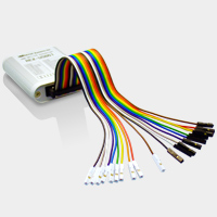
- USB61 SPI/I2C Protocol Emulator converts PC USB transactions to the SPI/I2C Bus.
USB61 enables you to easily control from a PC a variety of devices with SPI/I2C Bus.
This product includes SPI/I2C control utility software.
The SPI/I2C control utility can control SPI/I2C devices and GPO(General Purpose Output) signals.
It also can save setting parameter and logging data to the file. - MSRP US$198.00
System Requiremnets
Supportted Computer
- Windows PC with Hi-Speed USB(480Mbps) ports
Supported Operationg System
- Windows 8/7/Vista/XP
*Also works on 64bit version.
Specifications
Hardware specifications
| Host Interface | USB2.0 Full Speed Device | |
| Connector | USB mini B connector | |
| Voltage | 5V (via USB bus power) | |
| Consumption Current | 100mA | |
| Device Interface | SPI Master | Max. frequency 12MHz |
| I2C Master/Slave | Frequency 47KHz~1MHz | |
| Input/Output level | 3.3V/5V 1.8V/5.0V is enabled with external P/S | |
| Dimension | 2.24[W] x 2.95[D] x 0.71[H] in (57[W] x 75[D] x 18[H] mm) | |
| Weight | Approx. 0.213 oz (60g) (except cable) | |
| Operating environment | Temperature: 5 to 55 degrees Celsius Humidity: 20 to 80% (non condensing) |
|
| * REX-USB61 can only use 1 device. On the other hand, REX-USB61M can use multiple devices. | ||
Software List
| Title | Name | Description |
| Setting file | usb61.inf | For Windows Vista/XP/XP x64/2000 Setting file for REX-USB61 |
| Installer | Setup.exe | For Windows 8/7/7 x64/Vista 64 Installer |
| Utility | Usb61Uty.exe | Utility to control SPI/I2C |
| Script file | I2C_script.txt | REX-USB61 Batch Script file |
| SPI_script.txt | ||
| Sample code | EEPROMRWUty | Sample program to send/receive SPI/I2C |
| I2CSlaveSample | Sample program for I2C slave (VC6.0/VB6.0/VB2005/C#) | |
| Library | usb61api.dll | Library to control SPI/I2C devices |
| usb61def.h | Header file for Visual C | |
| usb61spi.bas | Module for Visual Basic | |
| usb51spi.vb | Code file for Visual Basic | |
| ActiveX control | usb61api.ocx | ActiveX control |
| Uninstall Utility | USB61_uninst.exe | For Windows Vista/XP/XP x64/2000 Utility to delete INF file |
Product Overview
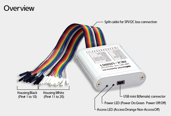
Cable Specifications
| Pin # |
Housing color |
Cable color |
Signal | Usage |
| 1 | Black | Brown | Power | Input/Output of power supply for a target device (Output 5V or 3.3V @100mA) (Input 1.8V - 5V ) |
| 2 | Black | Red | Power | Input/Output of power supply for a target device (Output 5V or 3.3V @100mA) (Input 1.8V - 5V ) |
| 3 | Black | Orage | 1MHz-SCL | Clock for I2C (401KHz - 1MHz bus voltage 5V only) (Pull-up resistance 10kΩ) |
| 4 | Black | Yellow | 1MHz-SDA | Data signal for I2C (401KHz - 1MHz bus voltage 5V only) (Pull-up resistance 10kΩ) |
| 5 | Black | Green | SCL | Clock for I2C (47KHz-400KHz 1.8-5V) (Pull-up resistance 10kΩ) |
| 6 | Black | Blue | SDA | Data signal for I2C (47KHz-400KHz 1.8-5V) (Pull-up resistance 10kΩ) |
| 7 | Black | Purple | SCK | Clock signal for SPI (12MHz 1.8 - 5V) |
| 8 | Black | Gray | SDO | Data out signal SPI (12MHz 1.8 - 5V) |
| 9 | Black | White | SDI | Data in signal SPI (12MHz 1.8 - 5V) |
| 10 | Black | Black | Reserve | N/A(Don’t use) |
| Pin # |
Housing color |
Cable color |
Signal | Usage |
| 11 | White (Gray) |
Brown | GND | Ground |
| 12 | White (Gray) |
Red | GND | IGround |
| 13 | White (Gray) |
Orage | DO0 | SS0 for SPI/PORT0 for I2C (1.8 - 5V) |
| 14 | White (Gray) |
Yellow | DO1 | SS1 for SPI/PORT1 for I2C (1.8 - 5V) |
| 15 | White (Gray) |
Green | DO2 | SS2 for SPI/PORT2 for I2C (1.8 - 5V) |
| 16 | White (Gray) |
Blue | DO3 | SS3 for SPI/PORT3 for I2C (1.8 - 5V) |
| 17 | White (Gray) |
Purple | GND | Ground |
| 18 | White (Gray) |
Gray | GND | Ground |
| 19 | White (Gray) |
White | N.C. | N.C. |
| 20 | White (Gray) |
Black | N.C. | N.C. |
Service & Support

- Manual / Drivers
all products