
- Run the SPI/I2C Analyzer on your PC.
- Easy to connect USB2.0 port.
- Capture the data on the SPI/I2C Bus.
- Can supply output power of up to 100mA.
- Supports input voltage from 1.8V to 5V.
- Works with USB Bus power.
- MSRP US$ 1,198.00
- Product Features
- System Requirements
- Specifications
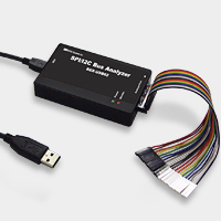
- Product Overview
Run the SPI/I2C Analyzer on your PC.
Using the USB62, your PC will br the SPI/I2C Bus analyzer.
USB62 SPI/I2C Bus Analyzer can analyze and monitor the device communiction on the SPI/I2C Bus.
It contains the equipment to analyze the SPI/I2C bus, and the application software for this.
When you start the application attached by connecting to the USB port of this product,
you can analyze the SPI/I2C communication with a PC.
Easy to connect USB2.0 port.
Easy to connect USB2.0 port on your PC.
Note: It does not work, when you connect to the USB1.1 port, Full-speed port
and the port except Hi-speed.
Capture the data on the SPI/I2C Bus.
Using the analyzer software which is included in this product, can display the data of Capturing on the SPI/I2C Bus.
- For the SPI Bus, can display with dump data for MOSI(Master Out Slave In) and MISO (Master In Slave Out) signal.
For the I2C Bus, can display with dump data for Start/Stop/ACK/NAK packet and only raw data.
Packet dialog
Dump dialog - When the capture buffer is full, it automatically stop the capturing.
Then analysis and display the captured data. - Save the captured data in the buffer to the file.
- Search the data in the captured data.
Serach the continuous data of up to 8 bytes.
For the I2C Bus, can search the device-address and NACK also. - When the trigger-in signal lines (TRGIN0 thru 4) will be a user-specified pattern, will start the capture.
Example) When the power of the device under the test is High.
When some terminal of GPIO signal is Low. - Set a filter by the device address, sub-address and the Read/Write direction,
and display only the communication data of the specified direction.
Display capture data with dump data
One-shot capturing
Saving the data to the file
Seaching the data in the captured data
The function of starting capture by external trigger
The function of filter display (For the I2C Bus only)
Analyzer mode: display transation timing.
This product has two modes of analyzer mode and monitor mode.
Depending on the function that you want to use, you use the mode properly.
Using the software "Switching tool of Analyzer / Monitor", can switch the analyzer mode and the monitor mode easily.
In analyzer mode, sampling the data of SPI/I2C Bus at the specified frequency.
This mode is for display the waveform of each transaction, and for checking of the Bus timing of the I2C communication.
Supports both I2C Bus mode master and slave.
- For the I2C Bus, can analyze at up to 4MHz.
(does not support HS protocol)
For the SPI Bus, can analyze at up to 16MHz.
- Sampling at up to 50MHz data on the SPI and I2C Bus, and
can display the waveform of clock and data line.
Sampling frequency can be selected from 10MHz/20MHZ/50MHz.
Can measure of up to 3 points per transaction basis..
- Can detect the device which is out of the provisions timing of the I2C Bus.
Can detect the device which is out of the timing specified by user.
>> display a larger image click on here <<
The function the analyzer mode own
Available frequency: I2C Bus - up to 4MHz, SPI Bus - up to 16MHz
Diaplay sampling waveform of each transaction
The function of checking for the I2C Bus timing
Monitor mode: Free-run Capturing and display.
At monitor mode, performs hardware decode for the data on the SPI/I2C Bus.
At this mode, using ring buffer, can capture on free-run.
- For the I2C Bus, can monitor at up to 1MHz. (does not support HS protocol)
For the SPI Bus, can monitor at up to 24MHz.
- When click the "Start capture" button, display the data on the screen in real time while capture the SPI/I2C Bus.
Until stop caputring by user, capture and display the data.
After buffer is full, the captured data will be overwritten starting with the oldest.
- For SPI communication, can set the specified data (up to 8 bytes) to start capturing.
For I2C communication, can set either the device address, the sub-address,
the specified data (up to 8 bytes) and NAK. Or can set combination of the
The function the monitor mode own
Available frequency: I2C Bus - 1MHz, SPI Bus - 24MHz
Free-run capturing and Real time display
The function of starting capture by trigger
Can supply output power of up to 100mA
This product can supply the output power of up to 100mA to the target device.
Supports the voltage of 1.8V, 2.5V, 3.3V and 5.0V.
Such as the device that runs independantly, it is useful in the case that the power can not supply on the host side.
Supports input voltage from 1.8V to 5V
Depending on the input voltage from the target device,
you can change the interface-voltage to between 1.8V to 5V.
Works with USB Bus power
This product can works with USB Bus power.
No need to connect the AC adapter.

- Manual & Drivers

